Tuesday, January 27, 2015

Final bits before painting.

I assisted Charlie today removing the above the waterline thru-hulls (3), all the tank vents (4) and the outflow for the shower drain. No real surprises or issues, just some moderate effort removing hoses and unscrewing the lock nuts.

Exhaust and bilge pump hru-hulls along with top of the rudder post bits:

DSC 0059

DSC 0058

Before we started in those items, I needed to get the last bolt out of the stem fitting. The cast aluminum stem fitting used 5 Phillips-head machine screws with nylock nuts to secure it. Because the hull layup in the pointed end of the hull/deck junction was fairly slap-dash, getting a purchase on the nuts was a trying exercise. In particular, the forward port machine screw did not want to come out. Last week we had fabricated a slim wrench to fit in the tiny space forward and used an impact drive to try to remove it. No luck, the threads were galled and the nut wouldn’t budge. Much swearing and grunting occurred...

I pulled out a 3/8” drill bit, chucked it into a corded drill and started in on drilling off the machine screw head. Not too tough, it just took a bit of time and lots of cooling shots of PB Blaster to get it broken. A few hammers on a drift and the screw shaft fell out.

After drilling:

DSC 0030

Next step, remove the stem fitting:

DSC 0045 

Bugs? Teeny-tiny birds nest?

DSC 0039

DSC 0054

From here on for the next couple of months, the hull will be in the hands of the yard, being prepped and then painted.

Although I feel like a turning point has been reached, and it has, there is still plenty for me to do while the boat is being painted. I have the new cabin sole to build and I am going to spend a fair amount of time refurbishing the wiring, running rigging and standing rigging on the mast.

Friday, January 23, 2015

In The Shed At Last

I met Charlie at the boatyard at 8:00 AM and we got right to work on removing the rudder. Neither of us was entirely certain how it was held on but it appeared that a stainless steel cap screwed onto the top of the rudder shaft. Initially when we tried to unscrew it we couldn’t. I posted a question to the always informative C&C list and got a couple of replies that confirmed that it should unscrew and the rudder should drop down.

Charlied fabricated a three inch fiberglass “socket” which fit over the cap and used one of the two set bolts to secure it. With that the cap unscrewed easily.

Unfortunately, the rudder didn’t drop. At all. Hmmmm.

We applied the tap it down method. No luck there either. Shook, turned and bumped it. Again no good. We started to think that the flat plate that secures the upper part of the shaft in line with the tube needed to be unscrewed also. That was physically impossible.

We scratched our heads a bit and kept on jiggling it. Ultimately it broke free and slid down. 

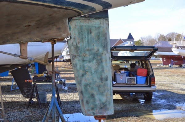
With all my other boats I have had to dig a hole in the yard to get the shaft clear of the hull but this time there was room to spare. One of the benefits of 6’8” draft I suppose.

Rudder out of the way:

DSC 0030

With that job done it was time to bring in the travel lift. Charlie wheeled that into place, led the straps and got ready to hoist. The owner of the yard came over to inspect my handiwork on the keel cradle and gave us his blessing to start the lift. The boat came up. And so did the keel. Stuck pretty firmly to the keel stub.

The yard owner, a man of much experience in running a yard and designing and building large powerboats walked over and started kicking and shoving the keel. As he was doing this we could see the hull/keel intersection start to open up. Shortly thereafter, with a significant crack, the keel feel away, Fortunately only about 4 inches. It settled right into place in the cradle and with that we just kept on hoisting the hull.

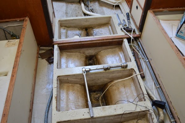
Okay, so the bilge wasn’t completely dry...

DSC 0065

What I had begun to suspect when I was grinding the hull/keel joint the day before turned out to be the case: when a previous owner had the bottom milled off for blisters and redone with epoxy, they must have dropped the keel too. And when they reattached it, instead of any sealant, they filled it with epoxy. The real world consequence of that was that there was no need to use a Sawzall to clear away the joint.

The final lift:

DSC 0068

No sealant for me, just epoxy if you please...

DSC 0071

One thing that the owner that had the bottom job done was that he either replaced or did not remove the butyl tape sealant around the keel bolts. There was absolutely no wasting of the keel bolts which was a tremendous relief to me. They appeared as clean and secure as the day they left the mold at Mars Keels. I will be using butyl when I re-attach the keel for certain.

Just need a bit of cleaning:

DSC 0085

So, finally, the hull, all 8,000 lb. of it, drove off to the shed.  Good to see it moving.

Backing down to the shed:

DSC 0078

The yard used to have two very large marine railways, none of which are in use any more. But one railway was left in place leading down into the first of two in line sheds. They built a railway carriage to hold boats and move them into and out of the shed with a small tractor. Pretty clever. This shed is insulated and heated so that operations can continue throughout the year.

Blocking the hull for work in the shed:

DSC 0130

DSC 0128

So, from here on I will be constrained on how much that I can do on the decks. Best estimate is that she will emerge with a fresh new coat of AwlCraft in around three months. Given temperatures and my schedules that is fine by me.

Inside the shed:

DSC 0147

DSC 0157

DSC 0163

DSC 0164  

DSC 0170

DSC 0172

It was long day for me, fraught with unknowns but ultimately it proved to be a pretty simple and easy procedure. May the rest of the project be the same...

Thursday, January 22, 2015

Okay, Maybe the Hull Comes Off Tomorrow...

It was a perfect day to pull the hull off of the keel this morning. Dense fog, near freezing, ice in the yard and on the boat and generally just a raw, cold, unfriendly kind of day.

Arrived at 8:00 and started pulling the covers off. I had to pump the bilge for a while due to lots of rain and being out of the country for almost 2 weeks. I measured the bolts; all of them except for one in the rear at 3/4”, were 1 1/2”. The boatyard had the appropriate sockets, 3/4” driver and pipe extension.

Manly Tools:

DSC 0077

I cleaned up the mess surrounding the bolts and started in on removing them. Phenomenally easy. So, either they were never torqued correctly or it’s just easy with something of that size. Either way, the bolts were off and out within 30 minutes.

After that I started in on grinding out the keel/hull joint while the yard worker started in on getting the rudder ready to drop. One thing that stood out for me was that there was not a lick of sealant between the keel and the keel stub. I expected to find some. Not sure what’s going one but I do know that a previous owner had the bottom shaved off and replaced with epoxy and what I think I see in the joint is lots of epoxy.

Keel/Hull Work:

DSC 0041

DSC 0070

DSC 0073

While I worked on the keel. Charlie, the boatyard guy, worked on getting the rudder ready to drop. He spent a lot of time under the cockpit. We soaked the bolts on the quadrant earlier with PB Blaster and hit them with the propane torch. It was pretty clear that they had never been touched since the boat rolled out of the factory in Canada. No real reason to suspect why they should have.

But as is usually the case with stainless steel bolts in aluminum threads, several decided that they didn’t want to budge. A couple of hours later the heads were cut off and the quadrant lay in pieces under the cockpit. As always with projects some things that seem easy end up being larger jobs than thought.

Now it’s much later in the day. After removing the two bolts securing the top-piece on the end of the rudder shaft we couldn’t move it. Ergo, the rudder remained firmly in place. After not forcing it but applying the just “getting a bigger rock” work method we were able to get it to start to unscrew. Which we hope is how it is attached….

Anyway, Charlie is going to make a tool to use for unscrewing it and we will get back to the job bright (hopefully) and early tomorrow.

Rudder that won’t drop:

DSC 0075


The Hull Starts To Comes Off

Another quick (and sporadic post) after being away from the boat for the past 6 weeks. Holidays, flu and medical mission work in the Dominican Republic. And cold weather.

Anyway, I had the bottom paint blasted off in early January prior to removing the keel.

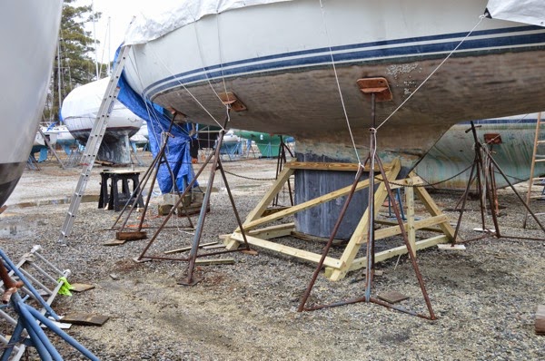
I spent the past day and a half frabricating bracing for the keel. Today we unbolt the keel, remove the rudder although I’m not sure about that one yet, and move the hull into the shed for painting.

Pictures of the bracing for now. 

Made out of pressure treated 4X4’s, 2X4’s and lag bolts.

First draft:

DSC 0043  

Final product:

DSC 0052DSC 0055

I’ll post pictures of the removal tonight. If all goes well...

Thursday, November 20, 2014

Cabin Sole Replacement - Round 2


About 13 years ago I replaced the entire cabin sole. As the boat was a bank repo, the original cabin sole was delaminating, worn out and in one place directly in front of the companionway steps, completely broken through. Since we had other priorities for the first couple of years, we screwed down a section of cheap plywood to keep folks from breaking their ankles and essentially ignored the condition of the rest of the flooring.

When we threw out all the original cushions and decided to have new ones made. The new cushions set against peeling plywood laminate was not going to impress folks. Or us.

We bought 15 yards of close-out Ultrasuede from close friends in the fabric business for an absurdly low price, contracted with a local boating canvas guru and had all new cushions made. From there it was on to replace the cabin sole.

I purchased two sheets of 18mm (~3/4”) x 4’ x 8’ teak-and-holly plywood and arranged to use the basement of a fellow racer and good friend since my condo rules probably weren’t going to allow me to stink up the place with varnish and epoxy fumes. I pulled the original flooring as templates and after sanding, epoxying, varnishing, cutting, routing and 1/4” x 3/4” teak edging that I had ripped, the flooring went in. It looked magnificent.

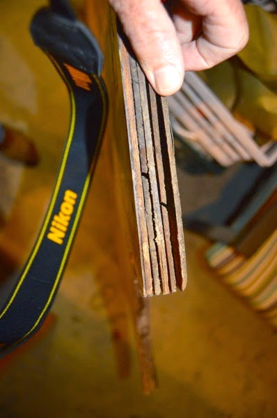
But. There were built in problems from the beginning. These issues finally reared their head after about 10 years of use.

When I didn’t do was, despite completely coating all the surfaces and edges with several coats of epoxy, was get ALL of the edges sealed. The reason for this is that I not so cleverly finished both sheets of plywood before making the cutouts. So, during the install phase, and when another good buddy who had done boat cabinetry gave me a hand, we just routed out out the shape and nailed the teak edging in place.

So, over the years and a few incidents of high water and just plain moisture in the bilge, the replacement cabin sole started to give up.

Replacement flooring gone bad:

DSC 0002

DSC 0003

DSC 0006

The weather has turned unseasonably cold so there is no more work to be done on the hull and decks. I purchased another two sheets of teak-and-holly plywood, which interestingly cost me less this time and brought them to my new shed. At least I won’t have to bother my old friend again. Especially given that he has stopped boating and gave me all his boat building supplies, of which there is a really nice vacuum pump along with all the sheeting and System Three epoxy that I could ever use. A good friend indeed.

So far, all that has been done is to layout the new and old plywood to make sure that things will line up and that the cuts will be correct. Pretty expense mistake if I get it wrong.

New and old plywood in the shed:

DSC 0020

Protecting the surface of the new plywood:

DSC 0041

Removing supports and screws:

DSC 0044

Checking alignment:

DSC 0051

Getting ready to trace the template outlines:

DSC 0056

That’s all the work that I did for the afternoon. In the next couple of days I expect to start cutting and routing. With the exception of West System epoxy, I don’t have any finishing product yet but I’m looking seriously at the new AwlBrite product in a semi-gloss. The original flooring was finished in many coats of gloss varnish and I’m not inclined to go that route again.

Thursday, November 6, 2014

Time Shift - Deck Repairs

Since I’m not posting on a continuum here, I thought I’d add a short post about what I found while doing some deck repairs. It was “interesting."

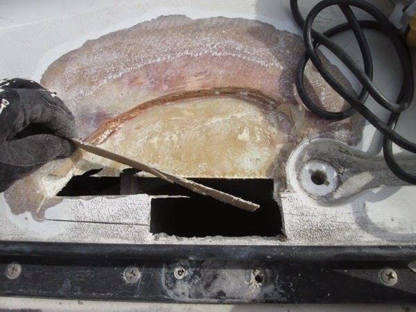
One of the former owners had done or had someone do some “quick” deck repair to the areas radiating out from the inboard ends of the stanchions that are used for the gates. On our boat we have gates port and starboard in line with the cockpit bulkhead. As stands to reason, as people, including me, grabbed them to haul themselves up or just to get aboard, the levering action seemed to have really put a lot of stress in that area. I assumed that the fix involved replacing core and adding fiberglass but that appears to not have been the case. It seems that essentially someone just ground out the stress cracks, filled them in and did a quick paint and non-skid cover.

Port side deck at lifeline gate:

IMG 0829

So after attacking the deck with my trusty grinder I discovered the good and the bad. 

The Bad: It seems that when C&C built the deck it smartly designed it so that the areas that are on top of the hull are solid glass. Good idea in theory. But what seems to have happened is that as the deck layup transitioned/tapered from the core areas to the solid glass areas, the overall thickness of the laminate became very thin. So what happened is that the area was prone to movement throughout. Constant springing whenever the stanchion was pulled on.

I would guess that the total thickness of the deck at the area where it overlaps the hull, just before and under the toe-rail to be at best 3/8” thick. In the area where there was still some coring, in this case some very thin foam, the bottom laminate layup was exceeding thin, maybe 1/16”.

Initial grinding and exposure:

IMG 0813

After cutting and removing the lower laminate schedule:

IMG 0824

So, the Good News: the core was dry! Even the plywood that was used instead of balsa core. Not sure if that was put in at the factory or if it was part of the initial repair. From the looks of it I think that the factory used plywood...

Anyway, I ground out the area on a 12-to-1 radius, based on the thickness of the top laminate layer, cleaned every thing up and formed sections of pre-made 1/4” FRP and epoxied them into place as replacement for the 1/2” balsa core.

First layup:

IMG 0827

While that section was curing, I moved over to the port side. Closer inspection lead me to believe that all that was compromised was the up level of the laminate that have a few stress cracks in it. It seemed to be a good bit stiffer that the starboard side so I decided to just grind out the area and re-glass it.

First look:

IMG 0830

When I was finished grinding and cleaning the area I cut sections of biaxial cloth along with as small section of 10 oz cloth and epoxied them into place.

Layout and epoxiing:

IMG 0835

IMG 0836

More to come after the epoxy sets up. Waiting for the rain to stop...


Sunday, November 2, 2014

Refurbishing the centerline table.

More from the “What I did last winter” photo archives.

The centerline folding leaf table in the main cabin was a mess from the day we bought the boat. And given other priorities it stayed that way while we used the boat. With the refit underway and while I was casting about for projects to complete last winter when I was unable to work on the boat while in the slip I pulled the table and went to work on it.

Like most of the woodwork and laminate on Ronin, it was in bad shape. The fiddles had been worked loose over time. The laminate was stained and dirty. The edge banding was peeling off and mostly gone. This was an easy fix and satisfying to do.

Table in rough shape:

IMG 3457

I removed the loose fiddles and set them aside. The piano hinges and most of the locking hardware was removed and the leaves set aside.

One thing that I did before doing the actual repair work was to sand the teak and give it a good teak oiling. There was a reason why did the teak oiling was first and I’m not sure why did it but it worked out okay.

Oiling the teak:

IMG 0331

IMG 0330

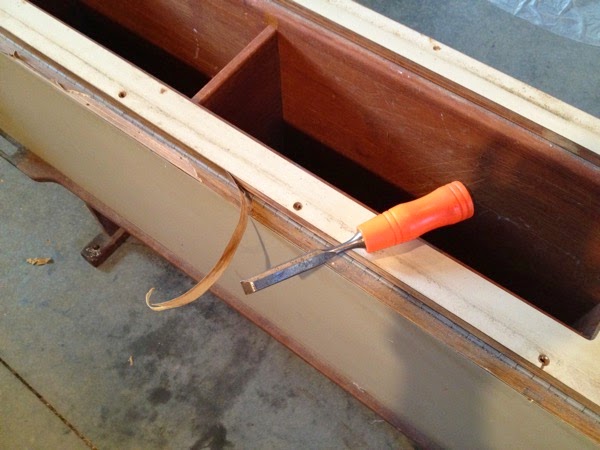
I removed all the original teak edge banding with a chisel and sanded the exposed plywood. I had ordered new teak edge banding and started in on applying it. Now, I didn’t RTFM, which I couldn’t find anyway in my mess of a shed so I used my heat gun to soften the pre-glueded strips as I slowly worked it down the line. It was only after completing the entire project that I found out that the way to apply it was to simply use a hot iron...

The hard(er) way of apply the edge banding:

IMG 3467

IMG 3507

The next step was to over-drill the worn out screw holes for the loose fiddles. I filled the oversized holes, gluing in short sections of wooden dowel and sanding them flush.

Prepping the old screw holes:

IMG 3506

Before I reinstalled the fiddles, I had to clean up the original laminate. Like the rest of the boat it was stained and dirty. Cleaning just wasn't working well enough for me so I decided to try something different. I sanded the laminate with a quarter-sheet sander and 220 grit sandpaper. For the corner work I used 3M scrub pads and sanding pads. Although some of the “texture” of the original laminate flattened out a bit, it came out looking like new. I was pleased with the results.

Cleaning up the laminate:

IMG 3484

IMG 3488

Along with the laminate sanding I took the sanding pads to the original chrome-plated fittings which were pitted and rough. That worked out well too.

Scrub away!:

IMG 3496

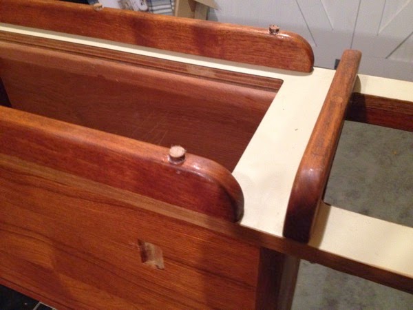
I was able to finally add the teak fiddles, pre-drilling and attaching them with all new screws and then gluing in new teak bungs that I made from some scrap teak that I had lying around.

Waiting for the chisel and some finish sanding:

IMG 3519

I didn’t take any pictures of the “final” product but it looks good and is in my attic waiting to be put back in the boat after I replace the cabin-sole. Another project for this coming winter...

A friendly little Black Widow spider kindly helping me with the table:

IMG 3473