Sunday, November 2, 2014

New Distribution Panels

Another project that I did last winter in my shed.

Part of the re-wiring project involved all new distribution panels for the navigation station. As I had mentioned earlier, the original panels were really showing their age. Not enough breakers for what I envisioned and even with the minimal items that we had there were several case of one breaker being used to service two or more loads. Not ideal.

The wiring was pulled and labeled and ready for the new panels. I chose Blue Sea Systems panels, specifically what they now refer to as their “Traditional Metal Panels.” When I bought them, the new “360” Panels were just being produced and were roughly twice the price. Sexier and a bit smaller but the traditional was fine by me.

The original factory distribution layout was composed of one 120V AC panel with AC Main and 3 positions. Functionally this panel was fine because it was only being used for the hot water heater and the cabin 120V AC outlets. The new panel will be have a Main and 6 positions but the bottom 3 will be for future use. Future use meaning if the new owners of the boat want to add a microwave or hot-tub...

On the DC side of the equation, the original setup had two panels of 6 positions each. Not quite enough and I had used single breakers to power dual devices in a few cases. I needed a few more positions so I opted for 3 panels of 6 positions each. Based on original plans for devices almost all of the breakers will be used.

Old “Temporary” panel:
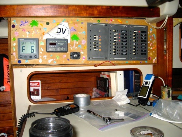
IMG 0876

Newer mockup distribution panel:

Photo 1

With a basic setup in mind I purchased some cheap 1/2” plywood from Lowes and ordered some, well, actually a half-sheet of Wilsonart kitchen countertop laminate in a interesting dark color and pattern.

With the mockup fitted to the space I cut the plywood and traced the cutout template. Using a hole saw and my trusty Bosch jigsaw I did the cutouts. With that done I spread on the contact cement and rolled on the laminate. After a day of letting the contact cement set up, I routed out the openings in the laminate.

IMG 3711

The panels were arranged and screwed into place along with base for the Link 20 and the Raymarine ST60 Multi repeater. Just to the right of the Multi readout I cut two holes for a basic 12V DC cigarette outlet and a dual USB outlet, both from Blue Sea Systems.

Panel under construction:
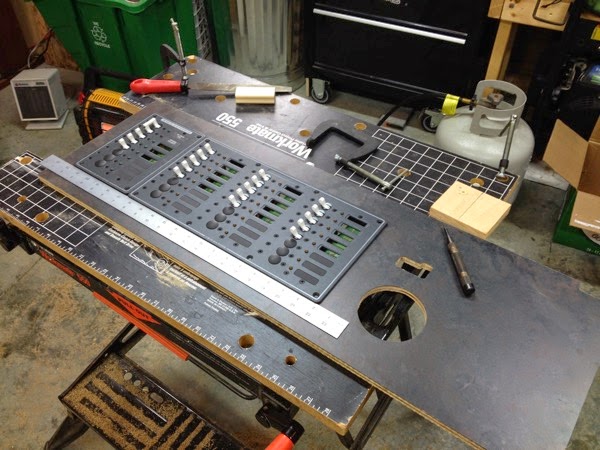
IMG 3727

IMG 3729

For this iteration I did not use the piano hinge that was on the temporary mockup because I’m not sure that this panel I was working will actually go into the boat. In all likelyhood on the final panel I will use a marine plywood and add the piano hinge on the bottom. The original panel installed by C&C required that each distribution panel be unscrewed and pulled out in order to get at the wiring. This was inconvenient and frustrating.

Semi-final distribution panel (with original hacked up melamine panel in front):

IMG 3831

First cut at assigning devices to breakers:

12VDC Layout Screenshot

Saturday, November 1, 2014

A Major Step Forward - Hardware Removal

In early August I started in on removing the deck hardware from Ronin in anticipation of prepping the decks for painting. While the boat was in the slip I started removing winches, cleats, turning blocks, track and pretty much anything that was secured to the deck. A old work buddy of mine, John, was in town from Kansas for few days and made the mistake of volunteering to help me. I needed it as some of the removal required two people.

By and large the hardware came off fairly easily. C&C did a good job of mounting and bedding the hardware. With the exception of the secondary winches and some rope clutches that a previous owner and I installed, all the holes were chamfered and butyl was used for the bedding compound. I’ve been very surprised by the lack of water infiltration into the core. So far almost of all the items that I have pulled have not had any rotten balsa core. I was expecting quite a bit worse but this says good things for the quality that C&C put into the deck hardware build. I know I won’t get away free but this means a lot less effort getting the decks ready for painting.

Jib tracks coming off:

Jib Track Coming Off

When I pulled the hardware there were a multitude of holes in the deck which is to be expected. I didn’t want to plug the holes with a dollop of clear silicone sealant like I had with the coach handrails that were pulled off over a year ago. I've read about the problems that silicone causes when trying to clean and prep the surface for painting.

So, in the vein of “better ideas”, I decided that just taping over the holes with duct tape would be fine. Pure lazy think. It did not work, So, after the first rainfall (outside and in…) filled my bilge I belatedly decided to pull the tape. I had cleverly applied the black Gorilla tape in the late summer heat. Think gooey, sticky mess when removing the tape.

One of several bad ideas that I’ve had:

IMG 0245

So, much scraping and wiping down with mineral spirits later, I had another brilliant idea: West System! Yup, I figured that since I was going to be sanding, repairing, glassing and epoxying the decks for painting anyway, why not just fill the holes with West System epoxy thickened with 407 Low Density thickener. Many swiped with a plastic squeegee later I had a very dry boat. Ugly but dry.

Chicken Pox:

IMG 0504

After a couple of days of intermittent work I had the big items off and ready for storage. Most of the items will go in my shed but some will stay outside with the boom and other large aluminum and steel parts.

Bucket ‘o Winches:

IMG 0169

I set one of the primary winches aside and a few days later put it on my workbench to check it out. Yeesh, what an un-serviced mess. Shame on me. So after doing a check to make sure everything was there and working, I stored them for a future maintenance project inside the warm and toasty shed when it’s cold outside and boat work slows.

Badly treated winches:

IMG 0248

IMG 0251

Monday, October 27, 2014

Anchor Windlass Shelf

I’ve been working on adding a Lewmar Pro-Series 1000 horizontal anchor windlass. Although my wife often insists on bringing up the anchor I figured it was time to have a proper anchoring system for the boat. I didn’t want the windlass to be sitting proud on the deck so I took some measurements of the anchor locker and worked up a rough CAD of a support structure inside the anchor locker and below the locker cover.

Design:

Bottom Bar Windlass Structure 2

After purchasing a sheet of 1/4” FRP flat stock and 6’ of 1/4” tube from McMaster-Carr I made some 2X4 and plywood mockups to ensure that things fit up. In addition to supporting and bearing some of the loads of the chain, the port side of the shelf will be used to mount a deck/anchor chain wash-down pump and hose.

IMG 3786


IMG 0067

After getting the mockups correct I cut the FRP and did some dry-fitting. Good thing because I was always finding errors and mistakes in my design. 

IMG 0114

With the parts cut and ready to go I started glassing in the transverse tube to the sides of the hull. The ends were fillet bonded and left to cure. When the fillet bond epoxy was set I applied fiberglass cloth using a mixture of West System epoxy and colloidal silica. 

IMG 0236

 The flat shelf of 1/4” FRP used to support the windless and wash down pump were then epoxied to the cross-beam and the struts tabbed and glassed to the bar, the shelf and then glassed to the bulkhead to add additional strength to the structure. Before doing any glass work though, I drilled the mounting holes for the windlass and associated wiring rather than deal with it after the structure was in place. Pretty tight fit in the anchor locker.

Dry fit of the windlass after windlass shelf installed:

IMG 4533

Final sanding and painting will be done next year when the decks are repainted.


Wednesday, October 22, 2014

Teak Companionway Trim Replacement

Another catch-up post on work that I did in my shed during the winter. 

The teak surrounding the companionway that the hatchboards fit in was in rough shape from the day we bought the boat. Now that I am repainting the decks it was time to fix the problem. The trim was so splintered and worn away that the hatch board rattled constantly.

So, $185.00 worth of teak later I was ready to start. Yes, if you look in the following picture you will see twice as much teak as necessary to replace the trim. I tend to make mistakes no matter how much I measure and measure again and, well, that’s where I’ll leave it.

Original teak trim and new stock: 

Teak Stock

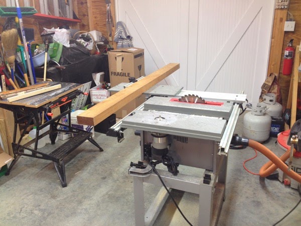
After taking lot’s of measurements and templates I practiced quite a bit using 2X4 pine stock. I’m no woodworker and this was my first important project where I used the Ryobi table saw I bought off Craigslist. And sure enough, I made a mistake with one of the trim pieces. That went into the teak leftover bin for future projects.

Teak stock, table saw, original trim and pine test piece:

IMG 3754

After much sawing, routing and dado cuts the trim was just about ready for dry-fitting. One of the tricky parts is that sailboats pretty much don’t have a square/straight line in them so each piece needed to be hand carved and fitted to the companionway. Although my final shaping was not perfect and some of the joints were not perfectly flush they came out pretty close and will have to do. I’m not trying to build a Hinckley.

Old and new trim places waiting for installation after the deck is repainted:

IMG 0257

IMG 0258

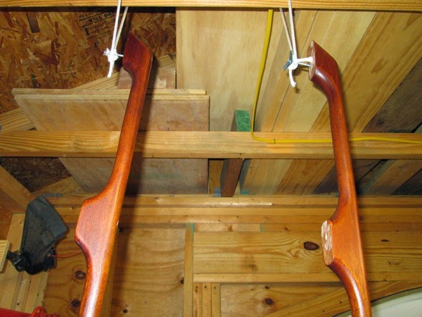
While I was working on the trim project I did some side work on the teak handrails for the companionway and the exterior cabin top handrails. I put around 10 to 15 coats of gloss varnish depending on location of the piece.  The interior overhead handrails received 12 coats of satin finish varnish. All are now sitting in the rafters of my shed waiting for installation. Some where in the future...

Cabin top and companionway handrails:

IMG 0004

Interior handrails drying:

IMG 0265

Starts and stops.

I’ve not posted in quite some time because my basic plan for adding updates to the blog was to post after some major job or task was completed. That plan isn’t going to work.

It’s become clear that because a number of factors have conspired to drag the rebuild process out I have decided to just start posting as projects progress.

The plans for this summer had me just about ready to start painting the decks. Forget that. The boat would have to come out of the water so that the mast could be pulled, the rudder shaft repaired and the keel dropped, cleaned up and the infamous C&C Smile fixed.

Now the boat is out of the water and sitting forlornly in the yard along with a whole of bunch of neglected yard queens. Technically the boat is scheduled to have the hull painted over the winter but given that a friend’s J40 was scheduled for the same treatment and went in the shed in November of last year and didn’t get completed and splashed until early this September, well, I’m pretty sure that we can say “Goodbye Summer 2016 Sailing Season…”. Eh, no worries.

Much of the slip in the schedule is on my part. Despite my delusions of cranking through projects on a daily basis this summer I’ve found that other demands have eaten up much of my time. Now, none of those demands were or are onerous, mostly motorcycle related fixes and trips, getting the dock wiring repaired so I could splash the Mako 261 and get her up to speed. And traveling. Lot’s and lot’s of traveling. We spent 10 days in Napa, CA and 2 weeks in Slovenia and Croatia, one week of that trip sailing the Adriatic off the Croatian coast. A week-long trip out to Moab in mid-September to do some dual-sport riding with my brother and old friends. In early October I was off to the Dominican Republic for some yearly volunteer work. Late October is filled with helping my sister-in-law with her yearly 100-mile endurance ride that she organizes. Kinda punches holes in my optomistic  schedule.

Anyway, I’ll start posting entries of projects underway. For the time being, some more non-sailing stuff.

Moab off-road riding:

IMG 4702

IMG 4708

Sunday, April 13, 2014

Sock Burning in Reedville

Although not a rebuild-related entry, I thought this would be fun to post.

We started our local version of Eastport Yacht Club’s annual Sock Burning celebration in Reedville several years ago. It started out with just few neighbors and friends from Annapolis and Norfolk standing around a small fire in our backyard down by the dock, drinking beer, eating some chili and clam chowder and finally pitching old socks into the fire.

We had a good time and have done it every spring since then, and as more folks have shown up in recent years, it has proven to be a crowd pleaser—rain or shine.

For those that may not know about the “tradition,” it got started in Eastport, Maryland, many years ago by a group of boatyard workers. As the story goes, they were looking around for a good reason to ditch their nasty old socks with the upcoming prospect of spring and warm weather. So they hit upon the idea to light a fire in a 50-gallon drum, buy a couple of cases of beer, and stand around drinking beer and burning their old socks.

It caught on and is now an event at the Annapolis Maritime Museum in Annapolis and has been mentioned in the New York Times.

Our celebration is timed to the closest Saturday to the spring equinox, generally around March 21, but this year we had a firm commitment for that weekend so we held it one week later, on March 29. One would have thought that that would ensure even warmer and nicer weather, but that was decidedly not the case. Temperatures hovered in the mid-50’s and it rained all day.

Cheap tarp, pop-up tent, new shed and a porch:

IMG 0029

A dreary day:

IMG 0031

Fortunately folks were pretty hardy and came by despite the weather. Sailors, after all, are used to being wet! With the combination of outdoor coverings, the back porch and a plywood and sawhorse table in the shed with a couple of heaters running, it proved to be okie-doke. A warm fire in the family room didn’t hurt either...

IMG 0026

After some steamed oysters, chili, clam chowder and excellent green and red mole provided by Bruce and Felix, the crew that built our new house, we got the show under way.

Friends Greg and Carie from Norfolk:

IMG 0021

Starting to burn ‘em:

IMG 0047

Friends and family pitching in:

IMG 0048

IMG 0049

IMG 0055

IMG 0057

We’ll be doing this again next year!

Monday, March 24, 2014

Nighttime Cabin Lighting

Having spent a bit of time sailing at night I have always enjoyed having low level red lighting down below. The off-watch isn’t generally bothered by it and it provides enough illumination so that going below to check on navigation while standing watch or to get some coffee, switching on a light is avoided. A friend of mine had red, or courtesy lighting as some call it, throughout his Oyster 48 which I came to really appreciate on deliveries and a race to Bermuda and the trip back.

So, I figured since I was up to my elbows in re-wiring I’d go ahead and add a courtesy/red light circuit to Ronin. Although I have upgraded the distribution panel to handle future circuits I knew that I didn’t want to put the breaker and switch on the panel at the navigation station. I knew that the other thing that I would want was the ability to turn the lights on at the entry to the cabin.

I purchased 5 Hella Flush Mount LED lamps for around $180.00. Essentially these lamps: 

2310 Large

I calculated the total length of the circuits and ordered enough of more than adequate 18 AWG wiring for the job. I already had enough connectors and heat-shrink tubing for the job as I buy them in bulk. Along with the wiring order I purchased a Blue Sea Systems Contura rocker switch.

I designated one of the four 24-hour circuit breaker positions in the new battery management panel as the power source for the LED circuit. From there I ran a length of wiring up to the behind the distribution panels to a bus bar in order to split the circuits out to either side of the boat.

Even though I ordered five lights with the intention of putting two in the main cabin, opposite each other in the base of the port and starboard settee, after doing some quick lighting checks with them and a 12VDC battery at night I decided that one light was all that was needed. Red light overkill.

First light at base of companionway steps.

IMG 4225 JPG

Next light at the base of the starboard settee:

IMG 4234 JPG

IMG 4237 JPG

The third red light in the very important head basin:

IMG 3963

The final light installed in the forward cabin under the v-berth:

IMG 3961

After running the wiring and getting most of the connections made I turned to start working on the companionway switch placement. The perfect location was in the side of the "little teak storage thingy” that used to cover the old instruments and now houses the autopilot CPU. It’s located to port and up high in the cabin at the companionway entrance. Perfect location to able to open the hatches, push the hatch cover back and flip the switch on so that there is lighting below even though the master switch hasn’t been switched on yet.

Prepping for the switch:

IMG 4525

And here is the storage box installed with the courtesy light switch being dry-fit:

IMG 4532

Anyway, since the boat hasn’t moved in 5 years, the lighting circuit hasn’t been put to use yet. Like all the other upgrades on the list. Someday...