Showing posts with label Plumbing. Show all posts

Saturday, February 2, 2019

Pulling (pushing?) PEX.

Part of the refit job involves updating the plumbing. In my planning software under Plumbing are items that encompass things like through-hulls, seacocks, bile pumps and hoses, head and holding tank updates and fixtures. You get the idea.

Years ago while doing cabin sole replacement number one, I managed to run a screw right into the high-pressure supply line to the head while fastening the cabin sole in place. It didn’t take too much time hearing the pump along with its favorite sister, the bilge pump laboring away to figure out that I had a problem.

So, being the “let’s get’er done quick” kind of guy that I am, I simply cut out a section of the original grey tubing, fitted a section of clear Shields polyester reinforced PVC hose, double, double hose clamped it ‘cause I found out that single hose clamps on a non-barbed fitting, well, don’t last too long. The fix is under the floorboards so out’a sight, out’a mind...

Now is the time to make things right. In addition to adding a new hot and cold cockpit shower to the system, I am replacing the faucets in the galley and the head. So rather than put a dirty sock on a clean foot, I decided to replace all the factory plumbing. This also aided with tying in my new hot-water tank.

I didn’t spend too much time evaluating material choices. I read of Onne van der Wal doing this on his Pearson 36 refit and the “PEX” solution seemed the easiest. I used 1/2” SeaTech polyethylene tubing and their line of connectors. I ordered them through the Paxton catalog that my yard uses and had them put the costs on my bill.

Being a noob to plumbing I will say that the job was pretty simple and straightforward. The revelation for me was the fact that the tubing is not terribly flexible. I was under the impression, delusion really, that the pipe could be contorted into all sorts of tight bends and angles. Not so. This required a bit more in the way of connectors, mostly elbows that I had not planned on when I drew up a schematic of the new system. Paxton and my yard were happy to remedy that shortcoming.

Pulling all the old tubing and running the new probably took about a day and a half. Not too much elbow grease necessary. Wherever possible I used insulated marine electrical cable clamps to secure the tubing and in some cases to shape the radius of a curve. Pro tip: buy the tube cutter. 

One item that I envisioned doing was to create a manifold for the freshwater supply from the two 30-gallon tanks located under each main-cabin settee. C&C’s original approach was to add a valve to the supply line on each tank. When one went dry I pulled up the settee cushions and switched it closed and the other tank I put in open. Pretty simple. But in my usual “turn a sow’s ear into a silk purse” I figured I could combine those two valves into one and be done with it.

The more I thought about where to put the manifold and the extra time it would take I realized that it wasn’t worth it to me. I’m not going voyaging and we don’t use the boat enough to justify it. And I am waaaaay behind on this project.

The only “manifold” that I did construct was for the high-pressure side that supplies hot and cold water. Because I was going from two to three high pressure supply lines, I constructed a manifold that distributed to each using stackable “T’s” and elbows. There was no need to incorporate any valves in these, especially since the whole structure would be under the floorboards.

One thing that I did do as sort of a lark was to incorporate valves into each fresh-water tank’s vent line. I’ve known of instances where saltwater intake in the tanks happened, generally on long legs at deep heel angles. We’ll see how that works in the real world of the Chesapeake Bay and coastal cruising. My money is on overkill...

Next up: installing the new faucets and shower.

Note: Red lines used for the F/W tank vents are due to me running out of blue...

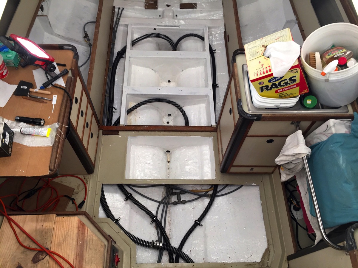
Old bilge old plumbing

Yuck….


FW tank fill shutoffNew filler hose with valve on vent line:

Starboard F/W tank hoses:

Starboard FW tank plumbing


Shot showing the fresh-water pump, expansion tank and hot-water heater hookups:

More PEX

Almost there:

Like the colors

And I will never see those line ID’s..
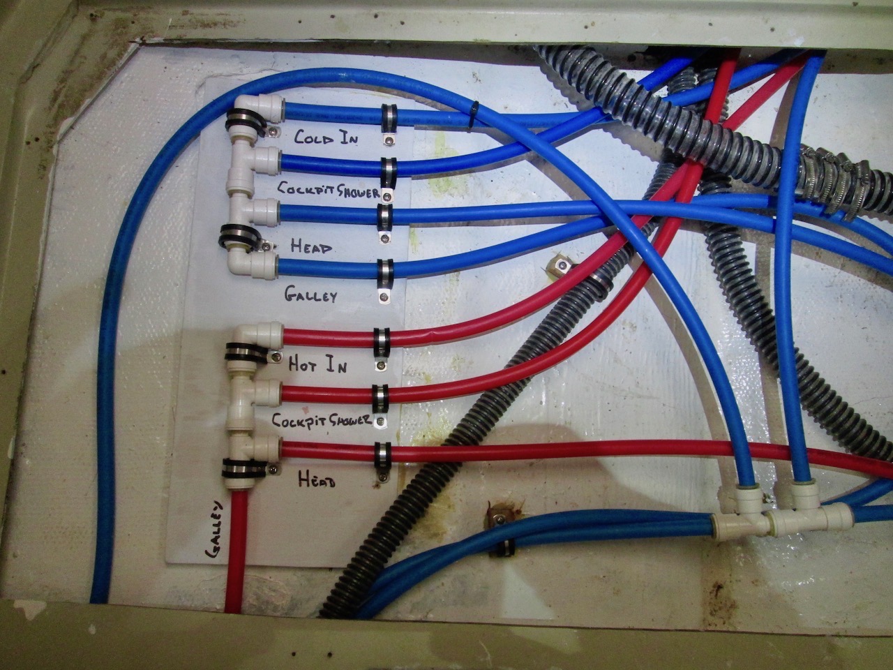
Completed manifold

Sunday, April 10, 2016

Houdini, hoses and a box.

Using the list of materials that I put together for the new and upgraded bilge pump systems, I pulled out the credit card and got to the real work. Ordering stuff. I’m good at that. Actually putting the stuff into and on the boat, Less so.

A few days later the hose that I ordered started to arrive. Three boxes of 50’ each, 1 inch, 1-1/8 inch and 1-1/2 inch respectively. With those in hand I cut segments of each and went over to the boatyard and had Charlie order some Scandvik 316 S.S. hose clamps and Ancor cushion clamps. Included in that order was a Forespar Marelon vented loop/siphon valve for the new Rule 2000 bilge pump system. Other orders coming in had new cockpit Marelon cockpit drains, two new Marelon thru-hulls, one for the existing manual Whale pump and the other for new Rule bilge pump. The Whale Super Sub Pump 650 pitched up on my porch too.

Armed with my "box o’ bilge supplies", I started making short trips to the yard to get some measurements and ideas of how to run things. In-between those trips and because the weather in the Mid-Atlantic region has been awful for weeks, I continued to work on the storage box project in my shed.

Taking the sheets of 3/16” FRP I ordered from McMaster-Carr, I cut out the side panels and a floor panel using an old dull table-saw blade. Worked pretty well actually. With the pieces  assembled I “tacked” the structure together using some West System Six10 that I had lying around. With that set up I ran some fillets along the inside corners using Awlfair so that there wouldn't be tight corners that were hard to clean.

Wear a respirator!

Cheap blade

Not enough sides

After getting the entire box put together I started applying strips of 4” tape along the edges to give it some structural integrity. That was a mistake. Trying to get a bond between the glass and the sharp corner was unpossbile. I stopped and set that project aside for later work.

Don’t try this at home.

Fail

So, back to the bilge systems. Like many of the items on the project list, I always assume that the effort required will be, well, effortless. 

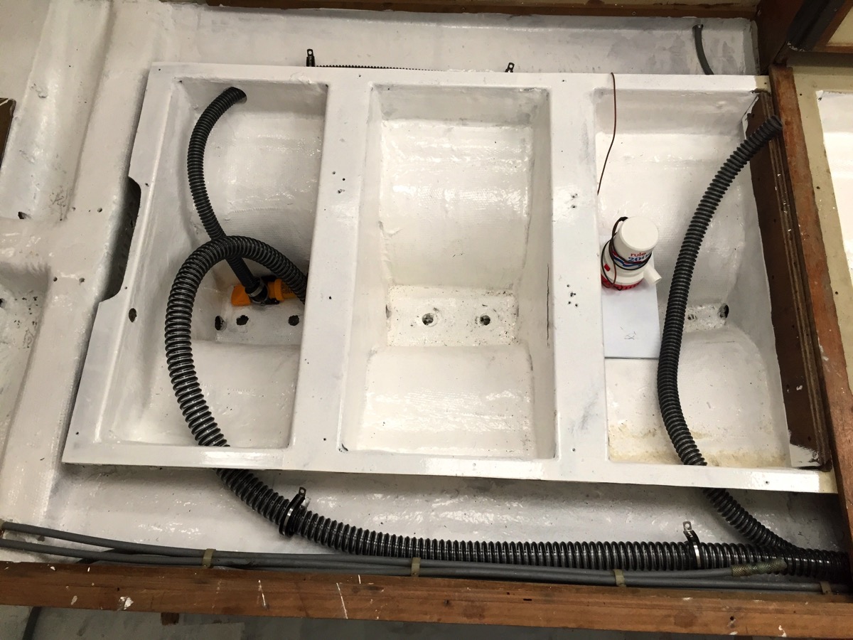
Pulling that new bilge hose put paid to that nonsense. Running the 1” line from the small Whale sump pump, no problem. Running the 1-1/8” line from the new Rule 2000 alongside the motor and aft to the transom, a bit more effort.

Then is was time to replace the 1-1/2” for the original Whale Gusher 10. Lord, that sucker kicked back. With a combination of external ribs, intrinsic stiffness and a very shallow bend angle, I spent 2 hours pushing and pulling. And to make matters worse, trying to run the same route as the original was a bust. Because the new hose was unable to navigate some tight turns it ended up kinking badly. I had to start sawing away at little bulkhead into the bilge in an effort to get a direct line through but that wasn’t going to work no matter what.

I also had to cut the hose in order to get (force) it through that opening. That hose size prefers to run in straight lines. One connector and four hose-clamps later I had the line rum from the front of the bilge back to the pump location near the wheel. And I have the scratched and bloody arms to prove it.

Starting to look okay.

Hole saw work

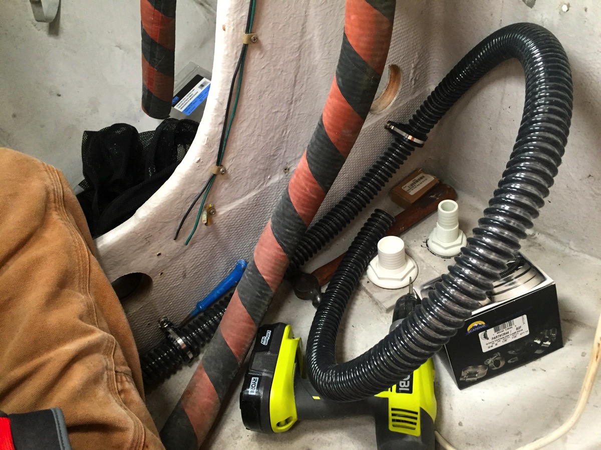
With the hoses pulled I started to dry-fit the connections and pumps. I placed the cushion clamps to get an idea of ideal locations but will not secure them until later when all the pumps and connections are finished.

Should work.

Clamp placement

More dry fitting

The next day I came back to the boat to start in on getting the new bilge pump system (Rule 2000) in order. To do this I needed to crawl underneath the cockpit and get to the stern. I’ve mentioned previously that this requires one be a top-level yoga instructor. And thin.

I grabbed as many tools and supplies that I figured I would need and started to contort and wiggle my way aft. Once there things went well. I pulled the hose and secured it in places with clamps. Those that went into core were drilled and filled with caulk. After that was done I started to figure out the placement of the vented loop. I thought that securing it to the stern would work fine. And it would except for the fact that the mounting screws would poke right through the transom and my new paint-job. Okay, time to stop.

I went home and grabbed some wood, cut and painted it so that the vented-loop screws into it. After the paint drys I will once again make the journey to the stern, epoxy it into place and when the epoxy cures, secure the hose.

Oh, and once that effort is done, I need to start obsessing about drilling a new hole in the hull for the discharge. Oh boy.

It’s stuffy in here.

Tight fit


Sunday, March 27, 2016

Planning takes more time than I thought.

Still working on the new and upgraded bilge pump systems. After measuring and climbing underneath the cockpit a week ago I started to finalize my thoughts about how to go about the project.

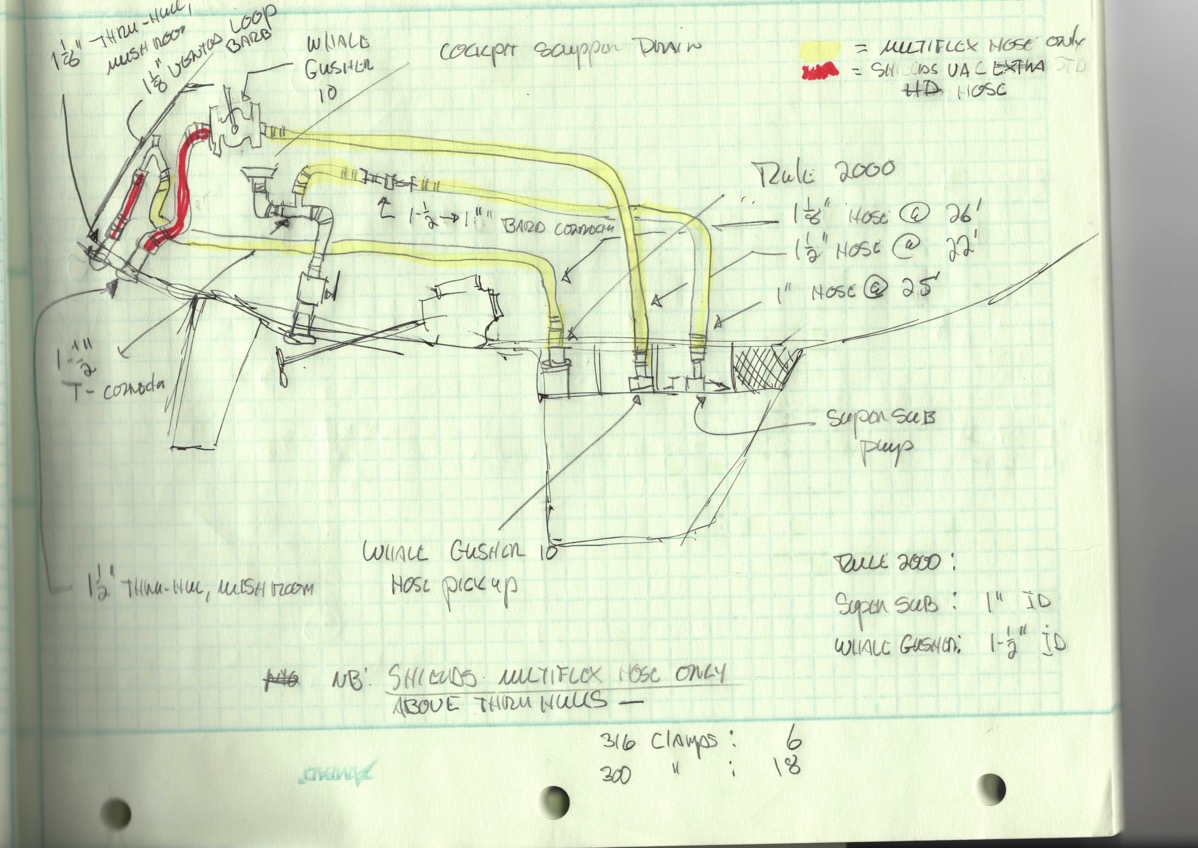
First thing that I knew I needed is a list of materials. I sat down and started with simple line drawings of the 3 basic systems and then got “creative” on the second iteration. In that plan I scoped out each length of hose and its diameter, any connectors and thru-hulls required, the pumps and types of hose clamps. After refining that a few times and finding simple mistakes I had my list of materials.

I gave the list to Charlie at the boatyard in the hopes that I could get some business steered that way but they had a hard time with some of the pricing. So I went out to some of my regular sources and started ordering. I should have most of the items this coming week.

On thing’s for sure, I going to have a good bit of bilge hose left over. In one case it was cheaper to buy an entire single 50’ roll for about 22’ and in another the 50’ roll price was exactly the same as buying 26’, each on a per foot basis. Maybe I’ll have some use for that hose in the future.

Not to scale:

Rough Plan

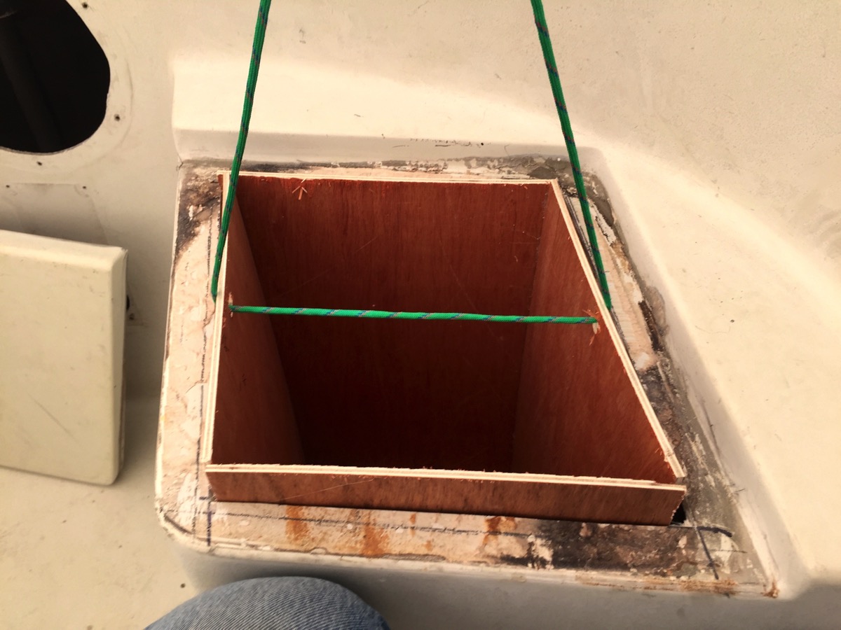
From there I returned to the new storage under the port helmsman’s seat project. I cutout and hot-glued together a box section of 1/4” luan plywood and gave it a quick test fit. It fit, perhaps even a bit loose. Once I was convinced of the feasibility of the modification I ordered up some 3/16” thick FRP sheet stock from McMaster-Carr. That order will show up this coming week also.

Crude but effective:

Scratch built

Slots in nicely:

Don t drop it

The real planning effort, one that I have rolled around in my head for quite some time without any great ideas springing forth is the hardware and rigging updates for the decks. This has to be done before I can start painting the decks and I’m pushing to get that going sometime in late May.

The boat has had a really jury-rigged setup for years and I’ve told myself that I would make it right. The problem is that I am not a really good “ideas” guy with it comes to this sort of thing. I’ve worked with pros and it’s clear that I’m not one.

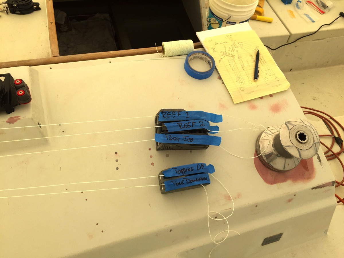
One of my primary goals has been to reduce the number of lines led aft to the cockpit in an effort to reduce clutter. As I’ve said, we don’t race this boat so quick and efficient line-handling isn’t critical. I was hoping to go from four cabin mounted winches down to two. That idea didn’t survive the hours I spent moving loose hardware around and running string to simulate line runs.

In the end, it was clear that I would need to bring the old Barient non-self tailing winches back to their original placement. And here’s the best part, I now have even more lines led aft. Clever...

Just keep at it:

Spider webs

Tape solves everthing

Old winch with blue tape

The way it was

After taking notes on the layout I spent an afternoon working up a rough schematic of the lines and equipment needed. That forced me to undertake an inventory of all the hardware that I had on hand. Some of it came off the boat and some was sitting in boxes in my shed.

Hope I didn’t cross lines:

Keep the costs down

Original hardware from the factory.

Unused old hardware

Some new and some newish:

New and old hardware

When I wasn't working on the boat project I did do some fun stuff.

Ninth Annual Sock Burning Party:

Socks burn nicely

Not quite 16 knots. Next time...

Fast is fun

Sunday, February 1, 2015

In the shed, Week 1.

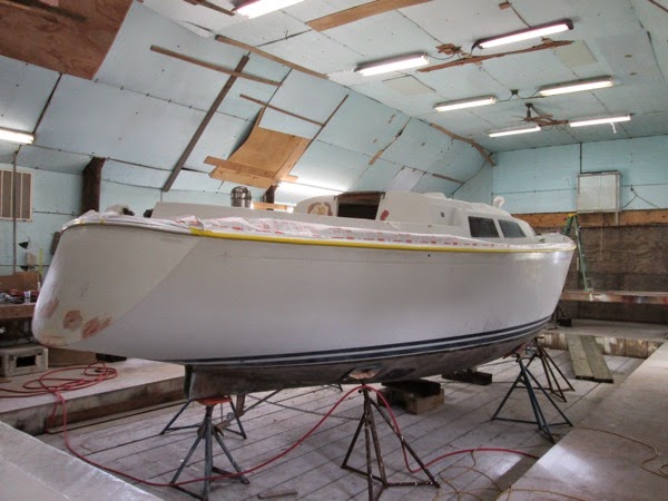
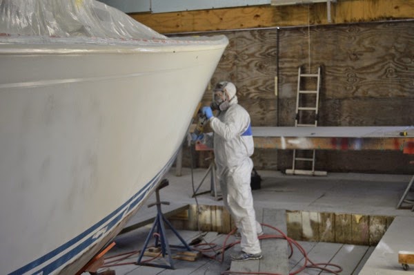
The hull has been in the shed for a week now and Charlie has started in on prepping the hull for painting. When we realized that removing the vinyl rub-rail was pretty much a non-starter, he ran a buffer with mineral spirits along it and despite some cuts and gouges it cleaned up pretty nicely.

The next step was a complete wash of the hull using Mean Green. Afterwards Charlie started taping the boat. Before he completed that I needed to get below the cockpit to look at the layout of the bilge lines and the cockpit scupper drains. This has been an area of annoyance for me since we bought the boat. The main bilge line using the manual Whale pump next to the wheel in the cockpit exits on the port side underneath the stern. The smaller electric bilge pump line snakes up from the bilge, extends over to the starboard side and then “Tee'd” in the starboard scupper drain just above the thru-hull fittings.

When I replaced the replaced the thru-hulls and seacocks some years back, because of the extended height of the seacocks, the hose run from the scupper drains was not direct and had a small sump. Because of this water never completely drained and if there was any debris it often developed a clog. To make matters worse, C&C designed deck level drains with a narrow grove to channel the water to a small scupper drain that led to a 6’ length of hose that, again, did not drain directly downhill. While in theory this seemed a great idea, those drains never did. These lines “Tee’d” into the scupper drains too. A mess.

Up, down and around:

IMG 0881

Going forward I plan on doing three things: 1.) running the electric bilge pump line directly to a new thru-hull near the existing manual bilge pump thru-hull, 2.) capping the two small scupper drains in the deck and removing the lines and 3.) removing the grey polypropylene fittings and ensuring that the cockpit scupper drain hose run downhill and free.

The reason for not completely removing and glassing in the shallow groves is that if in the future the boat is used for cruising and I want to catch rainwater, they can be plumbed to the port and starboard fresh-water tanks using small valves to open the flow after all the contaminants have run off.

The drain and channel; nice idea in theory but...

IMG 0244  Version 2

Manual bilge line running aft:

IMG 0886

After I finished scoping all that out, Charlie continued taping the boat. Afterwards sanding started. He mentioned that the gelcoat was “hard” and that it was taking longer to sand and using sanding disks at a pretty high rate. Oh well. In addition to sanding he spent some time grinding out any cracks and irregularities that he came across.

Taping:

IMG 0892

IMG 0894

Sanding and grinding:

DSC 0031

DSC 0036

An area of resin deficient layup near the bow: 

DSC 0038

Saturday, February 15, 2014

New Hot Water Heater

As mentioned in the previous post, the original Raritan hot water heater was on its last legs when we bought the boat. Over the years although it still heated water the tell-tale rust flakes and stains gave fair warning that some day it would need to be replaced. Surprisingly, even though it looked dead, it still worked when I finally unbolted it and pulled it out of the locker underneath the quarter berth as part of the re-fit/re-wiring job that I started several years ago.

One of the aspects of the hot-water heater that we wanted to change was to incorporate an engine driven heat-exchanger function. The original Raritan was a shore-power hot water heater only.

I researched manufacturers of marine water heaters and my eye was caught by the Isotherm line. I looked at the specs of their horizontally oriented units and realized that I could fit one of the 5-gallon models up in the outside part of the locker space in an area that was underutilized in the past. 

IMG 3606 JPGIMG 3623 JPG

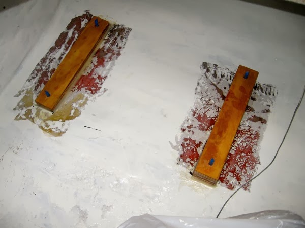
With the measurements and fitting finalized, I fabricated some mounts for the tank out of standard issue plywood, coating them will epoxy and fit some captive stainless steel bolts.

IMG 3772 JPG

As part of the general cleaning and painting of the locker space I ground off paint in the area for the mounts and epoxy them into place. A first coat of Interlux Bilgekote was already applied and ready for a second coat.

IMG 3780 JPG

The final mounting was pretty simple. Wiring and the plumbing awaits.

IMG 3831 JPG